Inquiry
Leave Your Message
0%

You might think automated inspection tools only check finished parts under bright factory lights, but that's really not the case anymore. These days, you’ve got cameras, laser sensors, X-ray systems, and measurement software that can examine products right on the production line, even as things are running. The right setup can quickly spot a misplaced label, a tiny hairline crack, or an out-of-spec dimension. But if you pick the wrong system, you risk triggering false rejects that can be pretty costly. So, yeah, every detail counts.

W. Edwards Deming, a real pioneer when it came to quality, once said, "Quality comes not from inspection, but from improvement of the production process." And that still hits home. While inspections can catch defects, they can’t really fix the process itself. That’s why it’s important to compare different manufacturers and their equipment, instead of treating everything as the same. For example, Cognex and Keyence are well-known for machine-vision solutions, while Hexagon leans more into measurement and metrology. Then you have Omron and SICK, which also provide sensing and inspection tech suitable for factories. Just keep in mind—what works best really depends on your specific needs, the products, and how you plan to integrate everything.

But let’s be honest—just putting a camera on the line isn’t the whole story. Lighting, resolution, how fast the inspection needs to be, software compatibility, and how well your team knows the system—these all play a huge role in getting accurate results. So, before you pick a system, it's smart to test it out with actual parts that are representative of what you produce. And it’s a good idea to set clear expectations on what level of errors are acceptable. This list I’ve put together should just be seen as a starting point, not the final decision. Because, in real life, things are often messier than what the product specs suggest. A closer look is definitely worth it.
Top 10 Automated Inspection Equipment Manufacturers

Automated Inspection Equipment: Core Technologies and System Architecture

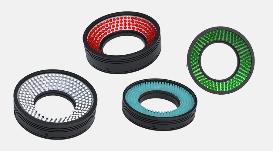
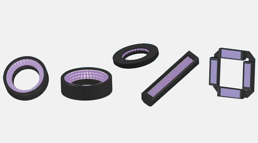
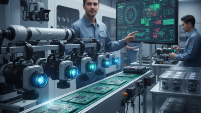
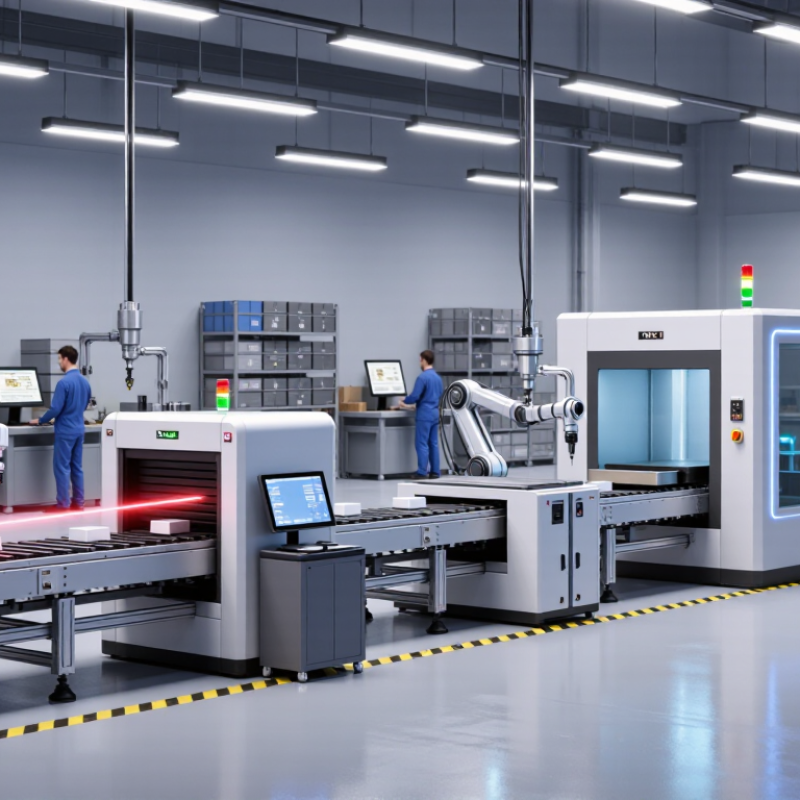
Automated inspection equipment combines optics, sensors, computing, and motion control into one coordinated system. A typical line uses a camera, a controlled light source, a trigger sensor, and an industrial computer. Each component has a clear job. The trigger captures an image when a part reaches a defined position. Lighting reveals surface features that ordinary room light can hide, such as shallow scratches or uneven edges. For reflective metal, angled illumination can reduce glare, though it may also hide defects on curved areas. Small details matter.

Image-processing software measures features against agreed tolerances. It may check dimensions, color, presence, or surface consistency, then send a pass-or-reject signal to a controller. Edge computing keeps decisions near the production line and can reduce delays. Meanwhile, inspection records help teams trace recurring faults and adjust upstream processes. Integration is rarely effortless. Camera positions shift, dust collects on lenses, and product variations challenge fixed thresholds. Regular calibration and sample testing help maintain dependable results. Still, no architecture catches every defect; teams must define what matters and review borderline cases rather than trusting a single score.

Inspection Workflow: From Sensor Capture to Defect Classification

An inspection workflow begins before an image reaches the screen. Sensors capture parts as they pass, while an encoder can link each frame to the product’s position on the line. Stable lighting matters: a slight change in angle may hide a scratch or make harmless texture look like a defect. Automated Vision Inspection systems therefore need repeatable exposure, focus, and calibration checks.

Small defects matter.

Captured images are processed to locate features such as edges, holes, or surface marks. Classification then assigns a result, such as pass, reject, or review, using rules or trained models. Clear thresholds help operators understand why a part was flagged. When comparing automated inspection equipment manufacturers, examine how well their systems connect capture, analysis, and production records—not just their advertised detection speed. False rejects can interrupt a line, while missed defects can weaken confidence in the process. Test with real parts, including worn, reflective, and slightly misaligned samples. A clean laboratory sample can mislead. Even a well-tuned system may struggle when materials or lighting change, so teams should review borderline cases and update settings carefully.

Top 10 Manufacturers Across Vision, Metrology, and NDT Equipment

Automated inspection manufacturers now compete across three distinct fields: machine vision, dimensional metrology, and nondestructive testing. MarketsandMarkets estimated the machine vision market at USD 12.29 billion in 2023, projecting USD 18.24 billion by 2028. That growth reflects demand for faster inspection, but speed alone does not prove a system is dependable.

A useful top-ten comparison should examine what equipment can measure, how consistently it performs, and whether results fit existing production workflows. In 3d Vision Inspection, check how systems handle reflective surfaces, fine edges, and changing part positions. Metrology platforms should be assessed for measurement repeatability and calibration practices. NDT equipment needs careful comparison of detection capability, inspection coverage, and operator requirements. Small differences matter. A missed edge can become a rejected batch.

Grand View Research valued the global NDT market at USD 23.57 billion in 2023 and forecast an 11.4% compound annual growth rate through 2030. These figures suggest strong investment, not a universal ranking of technical quality. Factory trials remain essential: vibration, dust, lighting shifts, and awkward part geometry can change real-world performance. Some comparisons still rely too heavily on headline specifications. That deserves a second look. For buyers, the strongest manufacturers are those that document test conditions and demonstrate results on representative parts.

Top 10 Automated Inspection Equipment Manufacturers - Top 10 Manufacturers Across Vision, Metrology, and NDT Equipment

Manufacturer-neutral overview of ten established automated inspection equipment categories. The entries describe equipment types and typical capabilities, not company rankings or vendor-specific specifications.

No. Equipment Category Core Technology Typical Inspection Data Common Applications Key Selection Consideration
1 2D Machine Vision Inspection System Area-scan camera, illumination, and image-processing software Presence or absence, dimensions in the image plane, surface defects, print and code readability Assembly verification, packaging, label inspection, and surface checks Image contrast, field of view, pixel resolution, lighting, and inspection speed
2 Line-Scan Vision System Line-scan camera synchronized with product or web motion Continuous two-dimensional images for detecting streaks, scratches, pattern defects, and edge variation Paper, film, textiles, metal strip, and other continuously moving materials Line rate, encoder synchronization, web speed, and consistent illumination
3 3D Laser Triangulation Scanner Laser-line projection with camera-based triangulation Surface profiles, height, step, gap, width, and selected geometric features Weld profiling, bead measurement, component inspection, and inline gauging Surface reflectivity, scan speed, working distance, and measurement uncertainty
4 Structured-Light 3D Scanner Projected patterns captured from one or more camera viewpoints Three-dimensional point clouds or meshes for surface form and dimensional comparison Part inspection, reverse engineering, and comparison with CAD data Part movement, occlusion, surface finish, calibration, and required spatial resolution
5 Coordinate Measuring Machine (CMM) Contact probing or optical sensors referenced to calibrated machine axes Coordinate points, distances, diameters, positions, and geometric tolerances Precision dimensional inspection of machined and manufactured components Measurement volume, probe configuration, workpiece setup, and environmental stability
6 Automated X-ray Inspection System X-ray transmission imaging with digital detectors Internal features and density-related indications, such as voids, inclusions, and component placement Electronics assembly, castings, batteries, and packaged products Material thickness, feature size, image contrast, shielding, and radiation-safety controls
7 Industrial X-ray CT System Multiple X-ray projections reconstructed into a three-dimensional volume Internal geometry, voids, inclusions, wall thickness, and dimensional characteristics Complex castings, additive-manufactured parts, assemblies, and research inspection Part size and density, voxel size, scan time, reconstruction settings, and inspection purpose
8 Automated Ultrasonic Inspection System High-frequency sound waves transmitted and received by contact or immersion probes Echo amplitude and time-of-flight information for locating internal discontinuities and measuring thickness Welds, plates, pipes, composites, and other volume-inspection tasks Material acoustics, probe frequency, coupling, scan coverage, and reference calibration
9 Eddy-Current Inspection System Electromagnetic induction using coils and conductive test materials Signal changes associated with surface or near-surface discontinuities, conductivity, or coating variation Conductive tubing, bars, aircraft components, and surface-crack screening Material conductivity, probe design, lift-off, part geometry, and calibration standards
10 Automated Magnetic-Particle Inspection System Magnetization of ferromagnetic parts followed by particle-based indication detection Surface and near-surface discontinuity indications, including crack-like patterns Ferromagnetic castings, forgings, welds, and safety-critical components Material suitability, magnetization direction, surface preparation, and inspection coverage

Machine-Vision Bandwidth: 1 Gb/s 1000BASE-T and Image Throughput

For automated inspection, 1 Gb/s 1000BASE-T provides a useful baseline, not a promise of full image speed. IEEE Std 802.3-2022 defines the Ethernet link rate; 1 Gb/s equals 125 MB/s before protocol overhead. A 1920 × 1200, 8-bit monochrome frame contains about 2.3 MB, giving a theoretical ceiling near 54 frames per second. Real throughput is lower because packets, camera settings, and host processing consume capacity. Small delays matter.

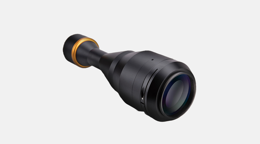
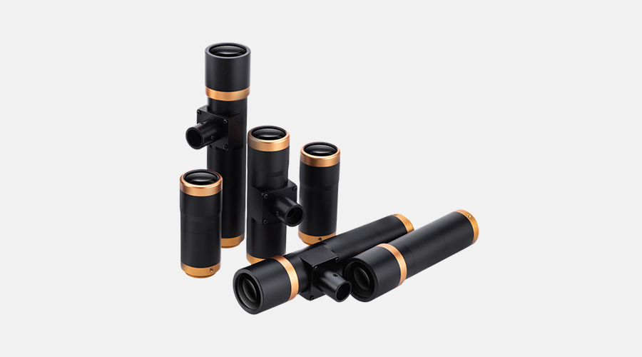
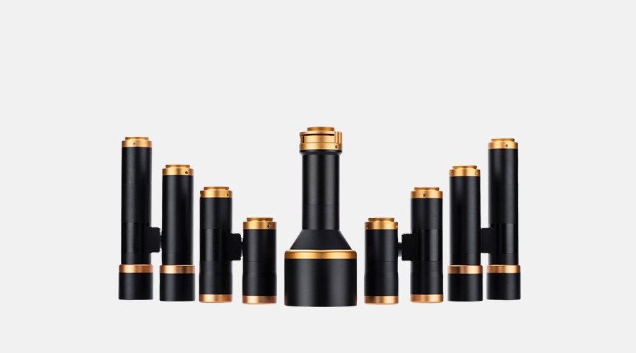
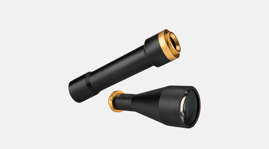
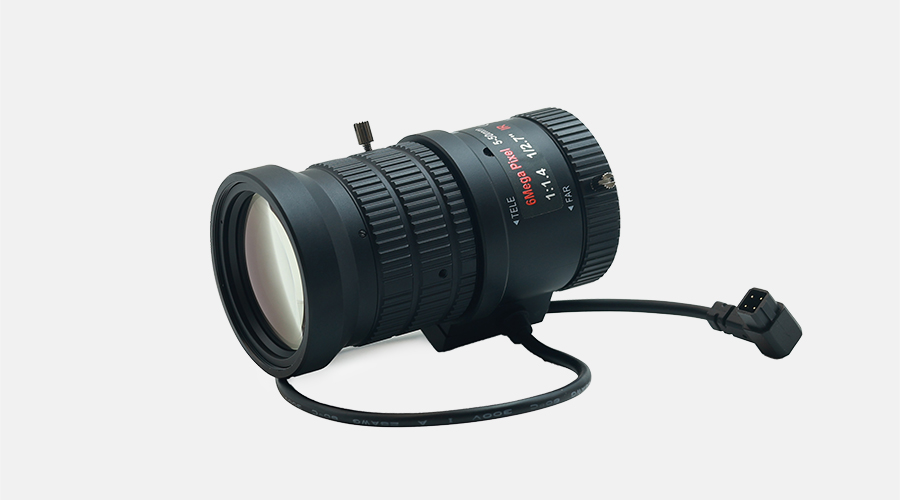
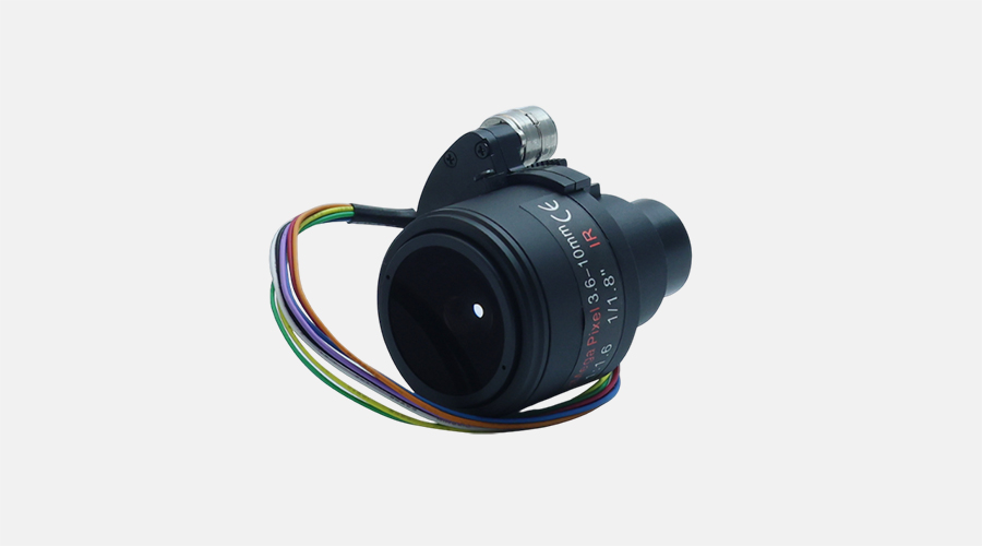
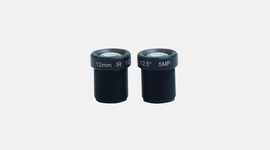
A Vision Inspection Lens can capture crisp details, but the network must carry every pixel reliably. Check frame size, pixel format, and packet settings together. For example, RGB data triples the bytes per pixel compared with monochrome. Measure sustained throughput on the actual inspection PC; a short test can hide drops during continuous production. I would treat calculated frame rates cautiously until tested under load.

Tips: Leave bandwidth headroom. Monitor dropped frames, not just link speed. IEEE 802.3-2022 is the technical reference for 1000BASE-T; your measured image payload depends on the full system, not the cable alone.

Dimensional Accuracy: ISO 10360-2:2009 CMM Acceptance and Reverification

Automated inspection equipment depends on reliable dimensional data, not just fast measurement cycles. ISO 10360-2:2009 defines acceptance and reverification tests for the length-measurement performance of coordinate measuring machines (CMMs). It gives manufacturers and users a shared way to assess whether a machine meets its stated specification. Small details matter.

The tests compare measured lengths with calibrated reference lengths at selected positions and orientations within the CMM’s working volume. Before testing, technicians should control temperature, allow the machine to stabilize, and check that reference artifacts are clean and correctly positioned. A loose fixture or a warm workpiece can distort results. The measured errors are assessed against the applicable maximum permissible error.

Acceptance testing checks performance when a CMM is newly installed or commissioned; reverification checks it again after use, service, or relocation. The standard does not remove the need for sound judgment. Test frequency should reflect workload, measurement risk, and environmental stability. A machine may pass on one day and still drift later. That is worth remembering when comparing inspection systems or planning quality checks.

Robot Cell Performance: ISO 9283:1998 Accuracy and Repeatability Metrics

When comparing automated inspection equipment manufacturers, look beyond headline speed and payload figures. ISO 9283:1998 provides a framework for measuring robot pose accuracy, pose repeatability, and path performance under stated test conditions. These figures describe different behaviors. Accuracy shows how closely the robot reaches a commanded position; repeatability shows how consistently it returns there.

A useful test report should identify payload, tool configuration, speed, approach direction, and environmental conditions. A robot may repeat a position within a tight range yet still miss the programmed point. That distinction matters when a camera checks a small connector or measures a narrow seam. Small differences matter. Ask whether results come from standardized testing or a production cell, where fixtures, cables, and vibration can change performance.

Robotic Vision Inspection also depends on calibration between the camera, robot, and workpiece. ISO 9283 values alone cannot predict image quality or defect detection rates. Request sample data from the intended operating range, including repeated measurements across the work area. Then verify performance with the actual lens, lighting, and part geometry. Test conditions are rarely perfect. That is worth admitting, because a specification without context can create false confidence.

FAQS

What components make up automated inspection equipment?

A typical system combines a camera, controlled lighting, a trigger sensor, and an industrial computer. Each component has a specific role.

Why is lighting important during inspection?

Angled light can reveal shallow scratches on reflective metal. Yet it may hide defects on curved surfaces. Small details matter.

How does an inspection system classify a part?

Software measures features such as edges, holes, color, or surface marks. It then assigns a pass, reject, or review result using rules or trained models.

How can teams reduce unreliable inspection results?

Keep exposure, focus, and camera position consistent. Clean dusty lenses, calibrate regularly, and test borderline parts. Not every defect is obvious.

Why should testing use real production samples?

Include worn, reflective, and slightly misaligned parts. Clean laboratory samples may not show how the system handles everyday variation.

What problems can false rejects and missed defects cause?

False rejects can interrupt production, while missed defects can weaken confidence in inspection. Review flagged samples instead of trusting one score.

What does edge computing do in an inspection line?

It keeps image decisions close to the production line, which can reduce delays. Records also help teams trace recurring faults.

How does ISO 10360-2:2009 relate to coordinate measuring machines?

It defines acceptance and reverification tests for CMM length-measurement performance. Tests compare measured lengths with calibrated reference lengths.

What conditions can affect CMM measurement results?

Temperature, machine stability, fixture position, and workpiece warmth can affect measurements. A machine may pass today and drift later. That deserves attention.

Conclusion

Automated Inspection combines machine vision, dimensional metrology, and non-destructive testing to assess products consistently and efficiently. A typical system brings together sensors, lighting, motion control, computing hardware, and analysis software. It captures images or measurements, processes the data, identifies potential defects, and classifies results for review or production decisions.

This overview explains how inspection equipment moves from sensor capture to defect classification and compares ten manufacturers across major equipment categories without focusing on brand names. It also examines practical performance considerations, including image throughput over 1 Gb/s 1000BASE-T connections, dimensional accuracy requirements under ISO 10360-2:2009 for coordinate measuring machines, and robot-cell accuracy and repeatability metrics described by ISO 9283:1998. Together, these topics provide a framework for understanding system capabilities, measurement reliability, and equipment selection.

Liam

Liam

Liam is a skilled marketing professional at New Vision, an innovative company that specializes in the production and sales of core components for machine vision. With a profound understanding of the intricacies of the machine vision industry, Liam excels at communicating the value of cutting-edge......
Previous 10 Machine Vision Quality Inspection Tips for Global Buyers?