Inquiry
Leave Your Message

Customised Industrial Lighting

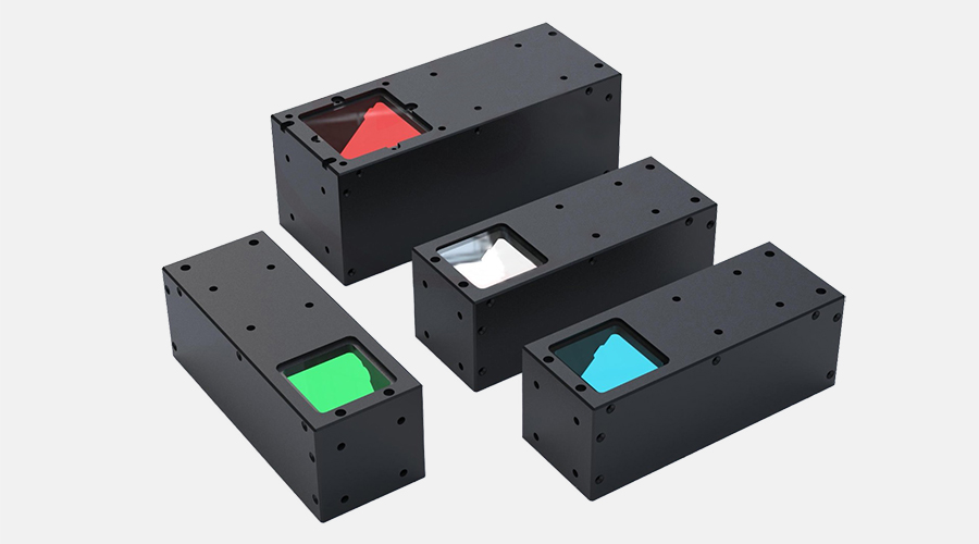
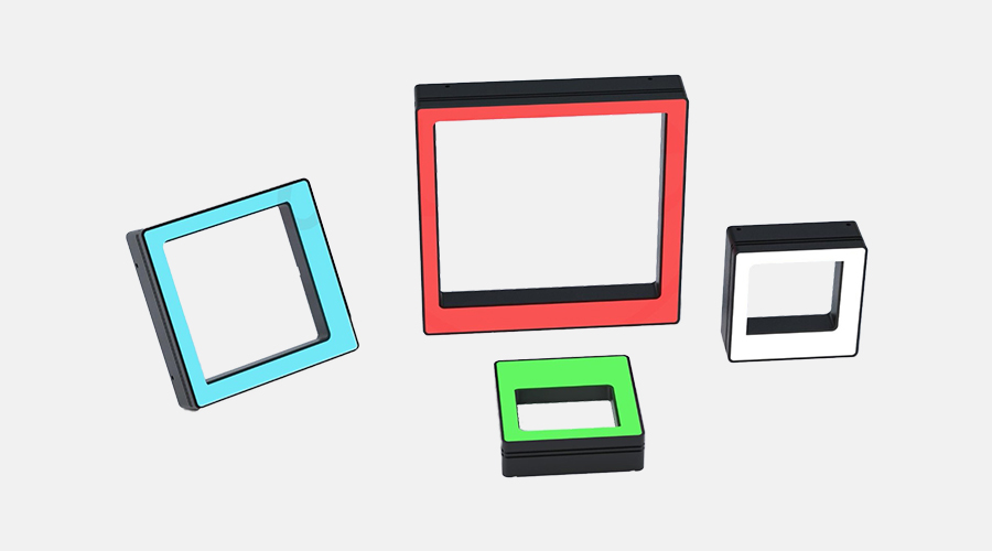
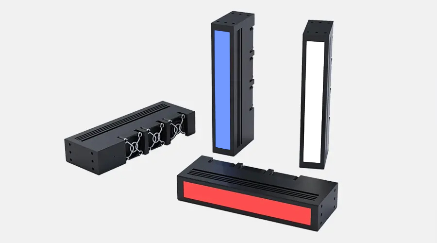
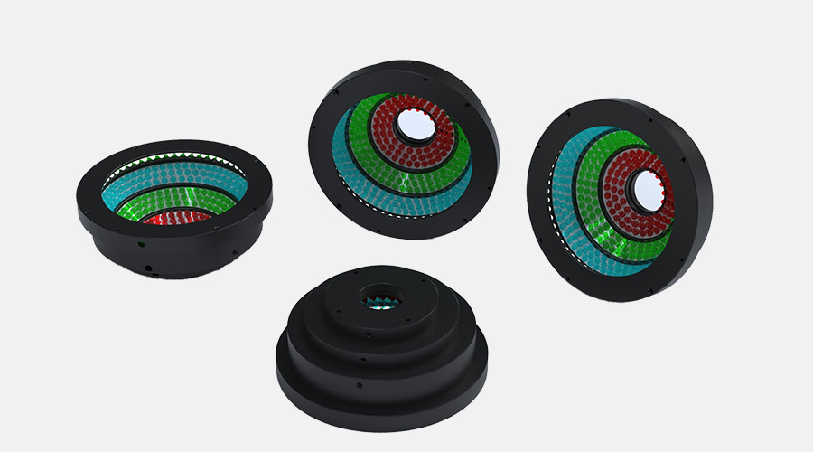
When customising industrial lighting, it is necessary to take into account the material of the workpiece, the inspection characteristics and the camera’s imaging conditions, whilst comprehensively considering the lighting configuration, light colour, wavelength, illumination angle, illumination area, power and control methods.

Which parameters of industrial illuminators are customizable? (Structures, dimensions, colors, multi-color combinations)

STEP 1

Light Source Configurations and Illumination Angles

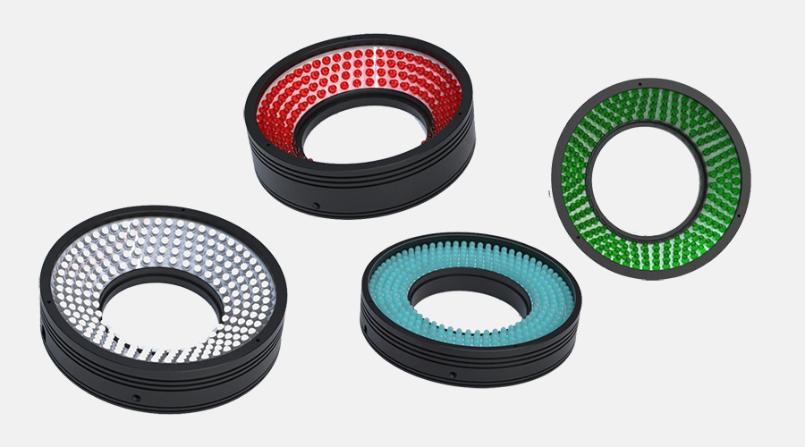
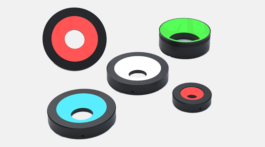
  • Ring light (0-90°)
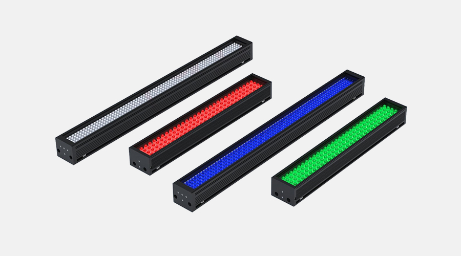
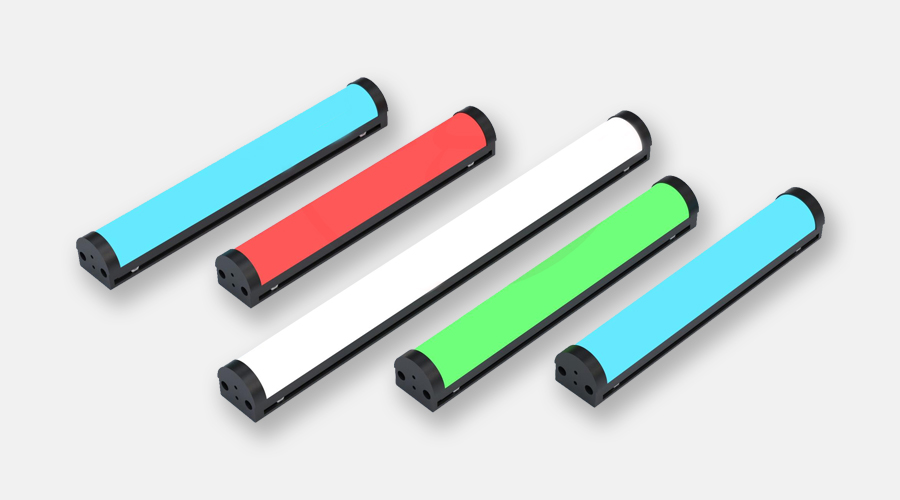
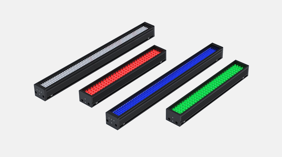
  • Bar light
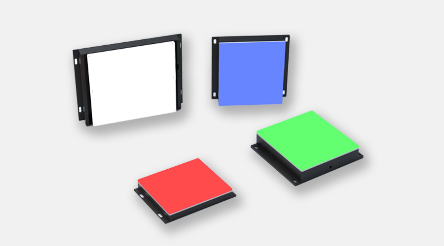
  • Backlight
  • Collimated backlight
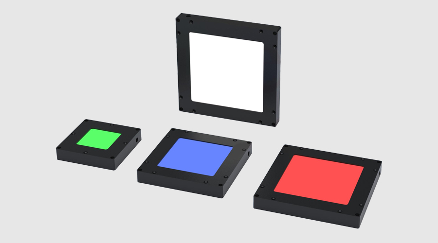
  • Hollow area light
  • Coaxial light (Standard coaxial, Parallel coaxial, Flat coaxial)
  • Dome light
  • Line scan light
  • AOI type

For example: The four-sided combined bar light of NV-BRF series features an adjustable illumination angle ranging from 0° to 90°. The NV-AOI series adopts multi-angle and multi-color LED arrays, with customizable luminous angle combinations. (AOI lights are generally used for solder joint inspection on PCB circuit boards; we currently only offer several models.)

Adjusting the incident direction changes the imaging performance of scratches, bumps, depressions, solder slopes and reflective regions. Sample tests are needed to find the optimal angle for highlighting target features. (PCB solder joint inspection usually takes place after SMT process. Such inspection equipment is dominated by South Korean and Japanese manufacturers; domestic suppliers are limited.)
STEP 2

Emission colour, colour temperature and operating wavelength

Red light:
620–630 nm
Green light:
525–530 nm
Blue light:
465–470 nm
White light:
colour temperature 6600–7000 K
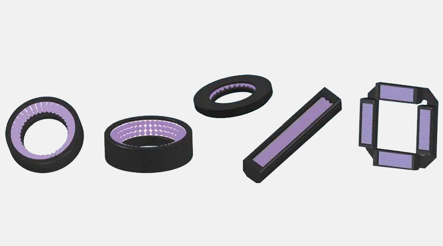
UV:
365–395 nm
IR:
850 / 940 nm

Attempt to enhance the contrast between the target features and the background based on the material’s reflective, absorptive, transmissive or fluorescent properties. Colour alone cannot guarantee the detection rate of specific defects.

STEP 3

Illuminated Area and Dimensions

  • +length
  • +width
  • +outer diameter
  • +aperture size
  • +thickness
  • +mounting hole positions

The length, width, outer diameter, aperture size, thickness and mounting hole positions of the lighting unit must be customised to suit the items to be inspected.

The effective illumination area shall cover the inspection FOV (10–20 mm reserved margin) for installation inside the equipment envelope.

STEP 4

Power Supply, Power and Brightness Control

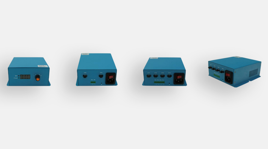
Adjust the brightness or trigger timing to minimise the risk of underexposure, overexposure and motion blur. Ultimately, the electrical compatibility between the light source and the controller must be verified.

STEP 5

Diffusion, Polarisation and Accessories

Adjust the light distribution according to requirements for reflectance, uniformity and brightness. Adding diffusion or polarising elements may result in some loss of luminous flux; therefore, both exposure and brightness must be checked simultaneously.

How can industrial light sources be customised based on inspection results?

STEP 1

Clear Contours and Edges

  • Key items for customization: luminous area, FOV, light divergence angle, illumination uniformity and lens matching, to achieve black-white contours for edge extraction. (Focus on dimension, luminous surface, workpiece reflectivity, bright-field / dark-field imaging.)

Series: NV-TH / NV-THP

The NV-TH series utilises a high-density LED array and a heat dissipation structure; the NV-THP series adjusts the light path using optical materials and is designed for scenarios requiring better parallelism and clear contours.

nv-th
low-angle-shadowless-ring-light-nv-fpr-series-1
STEP 2

Reducing strong reflections and localised shadows

  • When specifying, pay particular attention to the inner and outer diameters of the light source, the mounting height, the illumination angle, the diffusion structure and the direction of reflection from the workpiece.

Series: NV-FR / NV-FPR / NV-FDM

NV-FR, NV-FPR and NV-FDM shadowless ring lights and dome lights. These improve the illumination distribution on reflective surfaces through the use of light guides or multi-directional diffuse lighting; dome lights utilise a curved inner wall to create soft, multi-angled illumination.

STEP 3

Highlighting the slopes of solder joints and reflections from different directions

  • The NV-AOI multi-colour light source utilises a multi-angle, four-colour high-density LED array, with customisable combinations of illumination angles. When customising, particular attention should be paid to the RGB/RGBW configuration, the combination of illumination angles, the outer diameter of the light source, the mounting height, the brightness of each channel, and the camera’s exposure mode.

Series: NV-AOI

aoi-light-nv-aoi-series
bar-light-nv-br-series
STEP 4

Cover the long strip detection area and match the line-scan imaging

  • When customising the unit, please ensure you specify the scan width, light-emitting length, line-scan speed, exposure time, distance between the light source and the workpiece, heat dissipation requirements and trigger method.

Series: NV-BR

The NV-BR is used for line-scan cameras and reflective surface inspection. It is available in various light-emitting lengths and power configurations, and offers optional accessories such as diffusion plates, optical films and fans.